A potentiometer is a three-terminal resistor with a sliding or rotating contact that forms an adjustable voltage divider. If only two terminals are used, one end and the wiper, it acts as a variable resistor or rheostat.
I Circuit Symbol of Variable Resistor
The following table shows the most common resistor symbols in electronic design.
| variable resistor | sign |
| Potentiometer |
|
| Rheostat |  |
| Preset |  |
| Thermistor |  |
| Magnetoresistance | 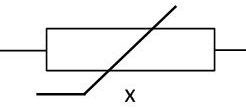 |
| Photoresistance | 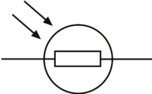 |
The symbol of the variable resistor is R (Resistance), and the unit is ohm (Ω). A variable resistor is a resistor whose resistance value can be adjusted, and is used in occasions where the circuit current needs to be adjusted or the circuit resistance value needs to be changed.
The variable resistor circuit symbol is based on the common resistor circuit symbol with an arrow to visually represent its variable resistance characteristics. Because a variable resistor is a varistor component with only two terminals, it is represented by only one lead and a broken line with an arrow, or a fixed resistor symbol with an arrow. As shown in Figures A, B, and C below.

In order to distinguish different types of resistors, several Latin letters are often used to denote resistor categories. The first letter R indicates resistance, the second letter indicates conductor material (T is carbon film, J is metal film, U is silicon carbon film, Y is metal oxide film, X is wire wound), and the third letter indicates shape Performance (X for size, J for precision, L for measurement, G for high power).
II Typical Structure of Variable Resistor
Knowing the structure of a variable resistor, it is easy to analyze its working principle. Figure 4 shows the structure of a small-signal variable resistor. As can be seen from the figure, it is mainly composed of a moving plate, a carbon film body, and three pins. The three pins are two fixed pins and one moving pin. The moving plate of the variable resistor can be rotated left and right. When we place a straight line, the contact points on the moving plate may slide over the resist or the plate insert a screwdriver into the adjustment port and rotate.
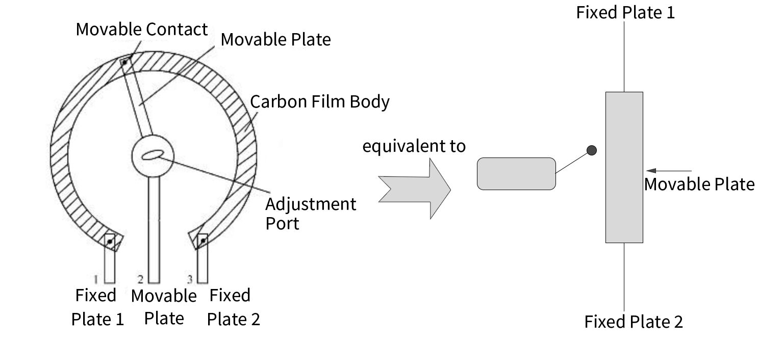
Use a flat-blade screwdriver to reach the adjustment position. When the screwdriver turns clockwise or counterclockwise, the moving plate will rotate accordingly. When the moving piece rotates counterclockwise (the moving piece moves upward in the equivalent circuit), the length of the resistor body between the fixed piece 1 and the moving piece decreases, and its resistance value decreases. As the length of the resistor body increases, its resistance value increases.
When the moving plate rotates to the leftmost position (the uppermost end), the resistance value between the fixed plate 1 and the moving pin is zero, and the resistance between the fixed plate 2 and the moving pin is the largest, which is equal to the nominal resistance of the variable resistor, which is two resistors between the fixed plates. When the moving plate slides to the far right (the lowest end), the resistance value between the fixed plate 2 and the moving pin is zero, and the resistance value between the moving plate 2 and the moving pin is zero. Plate and Fixed Plate 1 maximum, equal to the nominal resistance value.
III Classification of Variable Resistor
1. Film-type Variable Resistors
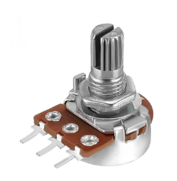
The fully sealed film variable resistor is also called solid variable resistor. Its resistor body is made of carbon black, quartz powder, organic adhesive and other materials mixed and pressed into the matrix of plastic or epoxy resin. , and then polymerized by heating. Its advantage is that it has good dustproof performance and rarely has poor contact failures.
(2) Semi-sealed membrane type
The manufacturing process of the resistor body of the semi-sealed film variable resistor is basically the same as that of the fully sealed variable resistor. The resistor adjustment of the semi-sealed film varistor is convenient, but the dustproof performance is not as good as that of the fully sealed film varistor.
(3) Non-sealed membrane type
Non-sealed film type variable resistors are also called chip adjustable resistors. completed. Its disadvantage is that the dustproof performance is poor, the contacts are easily oxidized, and the failure of poor contact with the synthetic carbon film is prone to occur.
IV Physical Characteristics of Variable Resistor
The resistor has two characteristics which are resistance and power dissipation capacity. The resistance can be expressed in ohms while the power dissipation capacity can be expressed as watt. Resistors are available for various purposes in the range of 0.01 Ω to 1012 Ω. The standard power ratings in which resistors are available widely is from 1/8 watt to 250 watts.
There cannot be a single resistor which can meet all our requirements. Thus, a different application needs a different type of resistor which possesses desired specification and tolerance suitable for that particular purpose.
V Basic Function of Variable Resistor
There are tons of used for variable resistors! Here's a few examples:
1.Volume control. On an electronic guitar you can use a potentiometer as a sort of voltage divider where the input signal goes to one end of the resistive film the other end goes to ground, and the wiper goes to the output. With the wiper set all the way to the end where your input is there's a very low resistance path from input to output. As you move the wiper toward the other end of the resistive film. The resistance between input and output grows, and attenuates the signal making it quieter, until you reach the other end where the wiper is closest to the end shorted to ground, which means the output is pretty close to shorted to ground, and the volume is off.
2.Similarly in a low pass or high pass filter a variable resistor can be used to change the cutoff frequency of the filter on the fly without changing components. This is done in much the same way as the volume control (you'll never guess where I first encountered this) on a guitar's passive tone control.
3.Probably the most common use of variable resistors is to fine tune a voltage divider, or a variable resistor sensor, like a photo resistor, thermal resistor, etc. Basically the setup is you make a voltage divider with a regular resistor and a variable resistor, the voltage drop across the bottom resistor can be used as a reference voltage, in which case you would want to use a potentiometer to dial in the exact voltage you want to use as a reference, or in the case of a sensor type variable resistor, you can set up a voltage divider, so when the voltage drop across the sensor reaches a certain point a separate circuit is enabled to do something else, often with the use of an op amp comparator.
VI Potentiometer--A Special Type of Variable Resistor
1. Types of Commonly-used Potentiometer
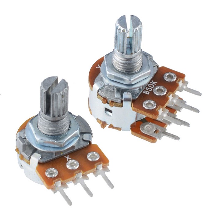
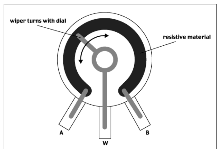
A variable resistor is called a potentiometer, or pot for short. It consists of a bare, fixed-resistance conductor with a terminal at each end, plus a conductive wiper arm that moves along the fixed resistor to provide different resistance values.
Pots are used as voltage dividers. If the wiper arm terminal is connected to one end of the fixed resistor, it is called a rheostat, and is used to adjust the current in a circuit.
Different kinds of potentiometers
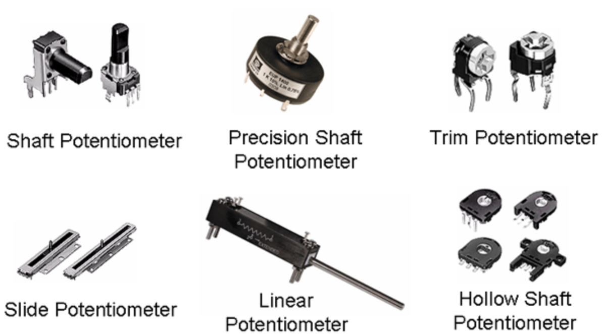
2. The use principle of potentiometer
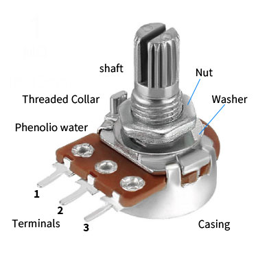
a. And here is a representation of what it looks like inside.
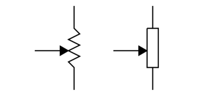
b. This is a pot’s schematic symbol, used in circuit diagrams. The US version is on the left; the international version is on the right.
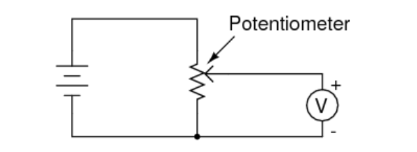
c. This is a voltage divider circuit. A battery is at left, a voltmeter at right. When the slider is moved to the bottom end, the voltmeter will read zero. As it’s moved toward the top end, the voltage read will increase until the slider reaches the top end, where the voltmeter will display the battery voltage.
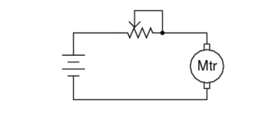
d. And here’s a pot wired as a rheostat, controlling the current to an electric motor (and thus the motor’s speed).


 Need Help?


