High Voltage Motor Driver - L298N Module
We are surrounded by motors and motor controls. A pioneer in the field of motor and motion control, STMicroelectronics offers a broad range of motor drivers that meet the requirements of brushed DC motors, stepper motors, and brushless DC motors over a wide range of rated voltages and currents.
L298N is a dedicated driver chip for dual full-bridge stepper motors, which contains 4-channel logic drive circuits. It is a dedicated driver for two-phase and four-phase stepper motors and can drive two two-phase or one four-phase stepper motor at the same time. , contains two H-bridge high-voltage, high-current dual full-bridge drivers, which receive standard TTL logic level signals, can drive stepper motors below 36V and 2A, and can directly adjust the output voltage through the power supply; this chip can be directly The analog timing signal is provided by the I/O port of the microcontroller. There are two enabled input terminals that can control the operation and cut-off of the two H-bridges respectively. The emitters of the transistors at the lower end of each bridge are connected, and a detection resistor is connected externally. Another logic supply input allows logic circuits to operate at lower voltages.
L298N adopts the Multiwatt15 package.
L298N is a motor driver that accepts high voltage, both the DC motor and stepper motor can be driven. It provides 2 amps of current from 5V to 35V and features thermal shutdown and feedback detection.
L298N can directly control the motor, set the rotation of the motor through the I/O output level of the main control chip, and then realize the forward and reverse drive of the motor. current drive conditions.

L298N module physical map
The freewheeling diode on the board can prevent the chip from being damaged by the reverse electromotive force of the motor coil when the power is off;
L298N is relatively hot during operation, so installing a heat sink can keep the chip temperature in a stable state and make the drive performance more stable;
This module integrates a power regulator chip 78M05. When your driving voltage is 7V~35V, that is, when 7V~35V is input at ① in the above figure, short circuit ② can enable the onboard 5V logic power supply, that is, introduce the input voltage at ① to pin 1 of the 78M05 chip , at this time, +5V can be output at ③, and the output +5V can be drawn for external use;
When ② is shorted, +5V can no longer be input at ③;
When ② is disconnected (not shorted with a jumper cap), the onboard +5V voltage can be provided by inputting +5V voltage at ③.
When ENA is enabled, IN1 IN2 controls OUT1 OUT2;
When ENB is enabled, IN3 IN4 controls OUT3 OUT4

L298N driver module circuit schematic diagram

L298N chip pin diagram
Pin 4 of L298N: Motor power supply Vs, provided by the voltage at ① of the L298N module;
Pin 9 of L298N: logic power supply Vss, provided by the voltage at ③ of the L298N module;
The electrical characteristics of L298N, the following parameters are what we are most concerned about:

Vs: Vih+2.5 ~ 46V
Vss: 4.5 ~ 7V, typical value 5V
Vil: input low level range -0.3~1.5V
Vih: input high level range 2.3~Vss
Ven=L: Enable pin low level range -0.3~1.5V
Ven=H: enable pin high level range 2.3~Vss
If you use a 3.3V MCU, then Vih=3.3V, so according to the manual, Vs recommends at least Vih+2.5 = 3.3 + 2.5 = 5.8V, so it is recommended that Vs not be lower than 6V.

Because the motor interferes a lot with the power supply during normal operation, if only one set of power supplies is used, it will affect the normal operation of the single-chip microcomputer, so we can choose a dual power supply for the power supply. One group supplies power to the microcontroller and the control circuit, and the other group supplies power to the motor.
Motor drive (obstacle avoidance) program design
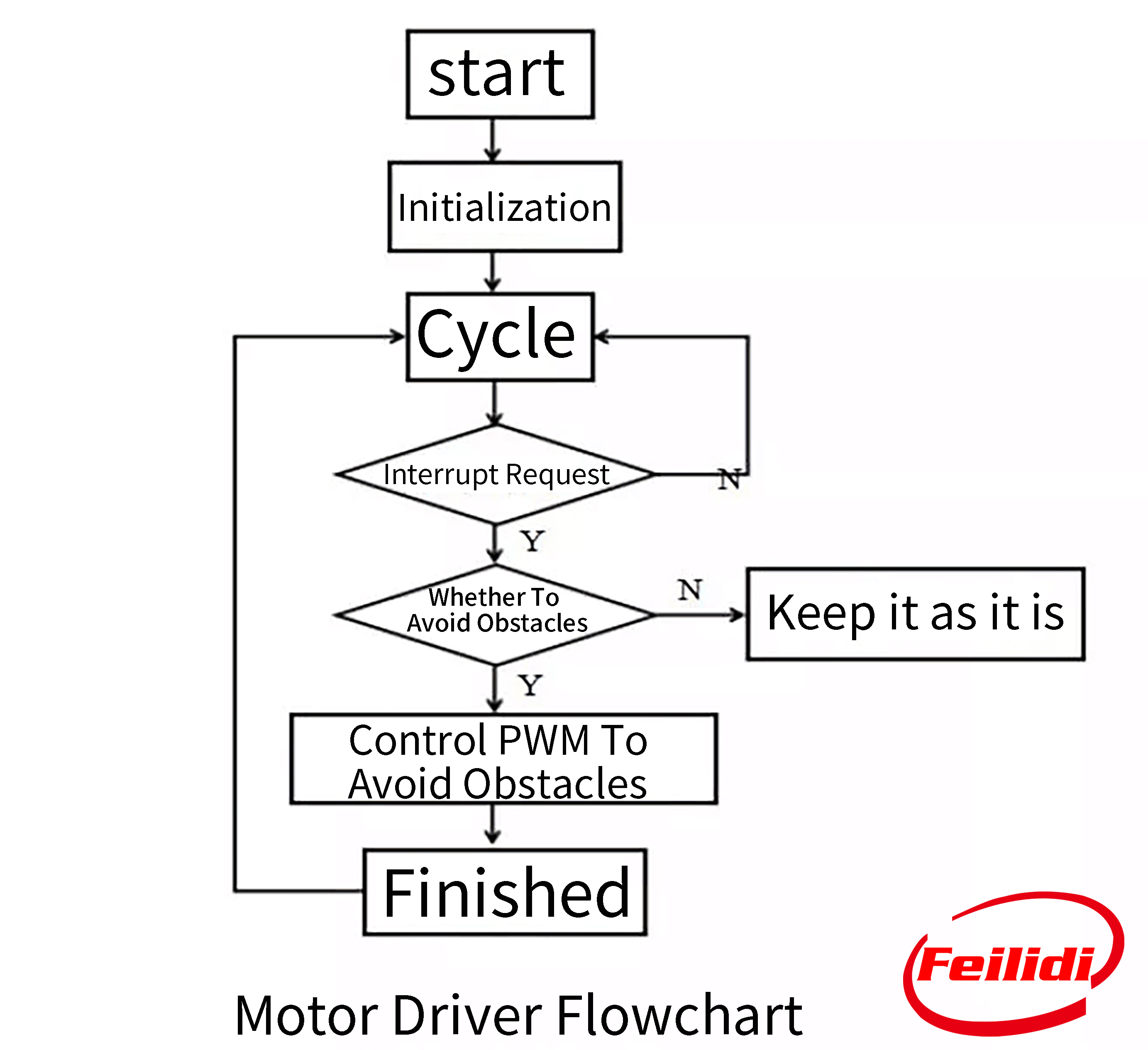
The flow of the motor driver program is shown in the figure. It begins to judge the interrupt request through the detection of the ultrasonic module and the infrared module. If there is no interrupt request, the original state will be maintained. If there is an interrupt request, the PWM will be adjusted to avoid obstacles or track motion. Through P1^3 level detection, it is assigned to temp, and according to the low four-bit level of P1, the corresponding driving level is given and sent to L298N, so as to control the actions of going straight and stopping, turning left and right, etc.


 Need Help?


