The photoresistor is essentially a pure resistive element, and its material is a semiconductor, with no positive or negative polarity. It can be used in either DC circuit or AC power circuit. Commonly used production materials are cadmium sulfide, and there are also materials such as selenium, aluminum sulfide, lead sulfide and bismuth sulfide. These materials have the property of rapidly reducing their resistance when exposed to light of a specific wavelength. This is because the carriers generated by illumination are involved in conduction and drift under the action of an external electric field. The electrons rush to the positive electrode of the power supply and the holes rush to the negative electrode of the power supply, thus causing the resistance of the photoresistor to drop rapidly.
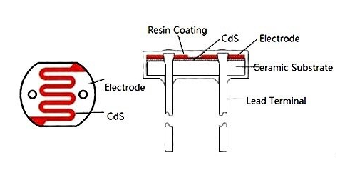
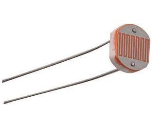
Usually, photoresistors are made into thin sheets to absorb more light energy. When it is illuminated by light, electron-hole pairs are excited in the semiconductor chip (photosensitive layer) and participate in conduction, increasing the current in the circuit. In order to obtain high sensitivity, the electrode of the photoresistor often adopts a comb-shaped pattern, which is formed by evaporating metals such as gold or indium on the photoconductive film under a certain mask. The general photoresistor structure is shown in the figure on the right.
Photoresistor usually consists of photosensitive layer, glass substrate (or resin moisture-proof film) and electrode. Photoresistors are represented by the letters "R" or "RL" or "RG" in the circuit
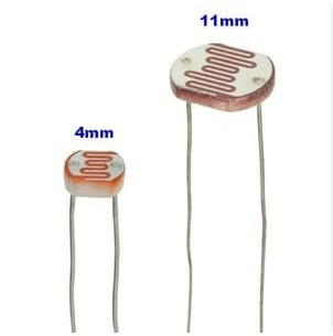
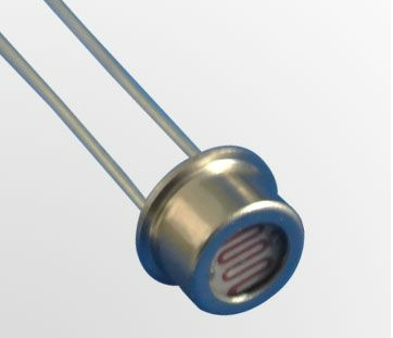
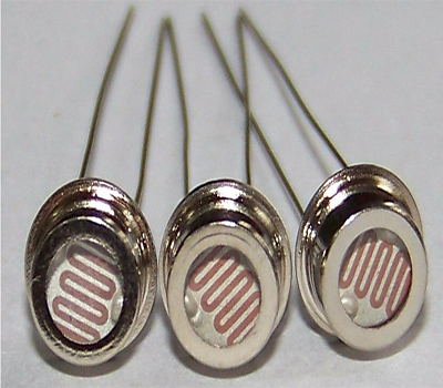
Photoresistors are often made of cadmium sulfide (CdS). It is divided into two types: epoxy resin encapsulation and metal encapsulation, both of which are wire type (DIP type). Epoxy resin encapsulation photoresistors are divided into Ø3mm, Ø4mm, Ø5mm, Ø7mm, Ø11mm, Ø12mm, Ø20mm, Ø25mm according to the diameter of the ceramic substrate.
How does a photoresistor work?
The photoresistor is a junctionless (PN junction) device, and its photosensitive properties mainly utilize the conductive properties of the photoconductor. When the photoresistor is illuminated by light, if the photon energy is greater than the bandgap width of the intrinsic semiconductor material, the electrons in the valence band absorb one photon, which is enough to jump to the conduction band and generate a free electron and a free hole. , thereby increasing its electrical conductivity and decreasing its resistance value. When the illumination stops, free electrons and holes gradually recombine, and the resistance returns to its original value. The resistance value of the photoresistor will change with the intensity of the incident light.
That is, when the incident light is strong, the resistance of the photoresistor will be significantly reduced; when the incident light becomes weak, the resistance of the photoresistor will be significantly increased.

Applications of photoresistor
Because photoresistors have the characteristics of small size, high sensitivity, stable performance, and low price, they have been widely used in automatic control and household appliances. Photoresistors are mainly used in various visible light light control circuits and various devices that require visible light light control. Can be widely used in cameras, solar garden lights, lawn lights, banknote detectors, quartz clocks, music cups, gift boxes, mini night lights, light and sound-activated switches, automatic street light switches and various light-controlled toys, light-controlled lighting, lamps and other lights Automatic switch control field.
1. Light control switch circuit
Light control switch circuits can be used in some public places such as corridors and street lights. Through the photoresistor, it will automatically turn on the light when it gets dark and turn it off when it gets light.
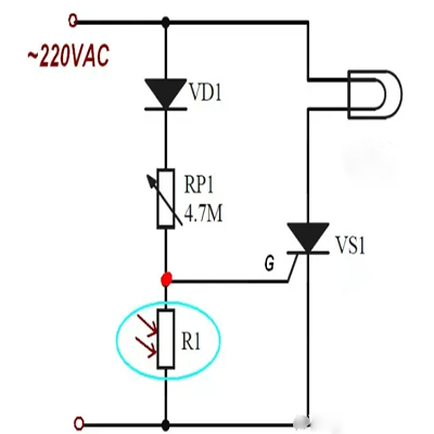
In the circuit, VS1 is a unidirectional thyristor and R1 is a photoresistor.
(1) When the light is bright, the resistance of photoresistor R1 is small. After the 220V AC voltage is rectified by VD1, it becomes a unidirectional pulsed DC voltage. This voltage is very small after being divided by RP1 and R1, and is added to the control electrode of thyristor VS1. The voltage is small, and the thyristor VS1 cannot conduct at this time, so there is no current in the HL lamp circuit and the lamp does not light up.
(2) When the light is dark, the resistance of photoresistor R1 is large, the voltage after dividing RP1 and R1 is large, and the voltage added to the control electrode of thyristor VS1 is large. At this time, thyristor VS1 enters the conducting state, so there is current in the HL lamp circuit As it flows through, the lamp lights up.
(3) Adjusting the resistance of resistor RP1 can change the divided output voltage of RP1 and R1, thereby changing the trigger voltage of thyristor VS1. This can adjust the degree to which the thyristor VS1 turns on when the light dims, that is, realizing the light Adjustment of lighting the lamp when it is dark.
If RP1 increases, a larger resistance value of R1 is required (the light is darker) to make the thyristor VS1 light up. On the contrary, reducing the resistance value of RP1 can light up the lamp when the light is not very dark.
2. Control circuit of photoresistor
In the circuit, R2 is a photoresistor, K is a relay, VT2 is a relay drive tube, and RP1 is a sensitivity adjustment variable resistor.
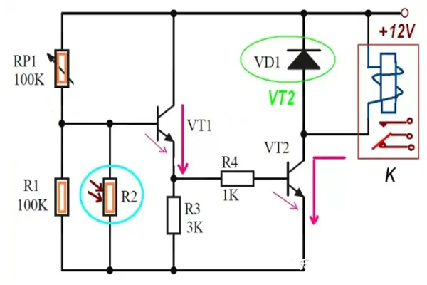
(1) Circuit when light is bright
When the light is bright, the resistance of the photoresistor R2 is relatively small. At this time, the output voltage of the voltage dividing circuit composed of RP1, R1, and R2 is relatively small, that is, the DC voltage added to the base of VT1 is relatively low, VT1 is in a cut-off state, and VT2 is also In the cut-off state, there is no current in the relay K and the relay will not act (the switch is open).
(2) Circuit when the light is dark
When the light is dark, the resistance of photoresistor R2 increases relatively large. At this time, the output voltage of the voltage dividing circuit composed of RP1, R1, and R2 is relatively large, that is, the DC voltage applied to the base of VT1 is relatively high, high enough to make VT1 in On state; VT1 emitter voltage is added to VT2 base through R4, VT2 is also in on state, current flows through relay K, and the relay operates (switch is closed).
(3) Changing the resistance of RP1 can adjust the sensitivity, that is, how dark the light must be for the relay to operate. When the resistance of RP1 decreases, the DC voltage of the base of VT1 increases, that is, the light is slightly darker and the resistance of R2 is slightly increased, which can cause the relay K to operate, so the sensitivity is increased, otherwise, the sensitivity is decreased.
3. Light brightness automatic adjustment circuit
Automatic brightness adjustment circuit, this circuit can automatically adjust the brightness of the light according to the intensity of external light. In the circuit, VS1 is a thyristor, N is a neon tube, HL is a fluorescent lamp, and R3 is a photoresistor.
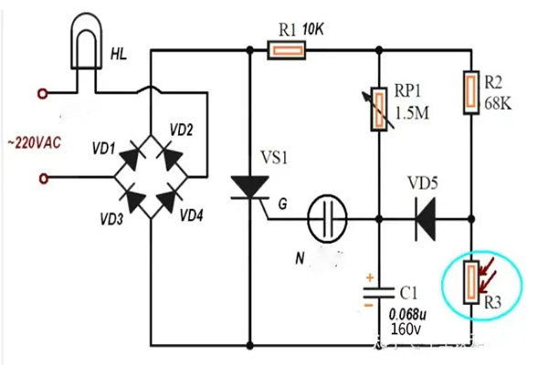
In the circuit, thyristor VS1 and diodes VD1~VD4 form a full-wave phase control circuit, and neon tube N is used as the trigger tube of VS1.
The 220V AC voltage is added to the VD1~VD4 bridge rectifier circuit through the load HL. The rectified unidirectional pulse DC voltage is added between the anode and cathode of the thyristor VS1. The turn-on and cut-off of VS1 are controlled by the voltage on the control electrode. The rectified voltage is also added to each resistor and capacitor.
The DC voltage charges the capacitor C1 through R1 and RP1, and the voltage charged on C1 is added to the control electrode of the thyristor VS1 through the neon tube N; when the voltage on C1 rises to a certain level, the neon tube N turns on and increases the voltage. to the control electrode of thyristor VS1, causing thyristor VS1 to conduct and the lamp HL to light up.
(In addition to R1 and RP1, the charging circuit of C1 also has R2, R3, and VD5. The divided voltage of R2 and R3 turns on VD5 and also charges C1, so the resistance of R3 can determine the charging voltage on C1. The size can also determine the average conduction time of VS1 within one cycle of AC power, so that the brightness of the lamp can be automatically controlled.)
(1) When the external brightness is high, the resistance of photoresistor R3 is small, the charging voltage of C1 is low, the average conduction time of thyristor VS1 is short, and the HL light is dark.
(2) When the external brightness is low, the resistance of photoresistor R3 is large, the charging voltage of C1 is high, the average conduction time of thyristor VS1 is long, and the HL light turns on.
(3) Since the resistance of R3 automatically changes with the intensity of external light, the brightness of the lamp HL is also automatically controlled by the intensity of external light.
(4) Adjusting the resistance of variable resistor RP1 can change the charging time constant of capacitor C1, that is, change the conduction angle of VS1 and adjust the brightness of HL light.
Classification of photoresistor
According to the spectral characteristics of photoresistors, they can be divided into three types of photoresistors:
UV photoresistor
Sensitive to ultraviolet rays, including cadmium sulfide, cadmium selenide photoresistors, etc., used to detect ultraviolet rays.
Infrared photoresistor
Mainly include lead sulfide, lead telluride and lead selenide. Photoresistors such as indium antimonide are widely used in missile guidance, astronomical detection, non-contact measurement, human disease detection, infrared spectroscopy, infrared communications and other national defense, scientific research and industrial and agricultural production.
visible light photoresistor
Including selenium, cadmium sulfide, cadmium selenide, cadmium telluride, gallium arsenide, silicon, germanium, zinc sulfide photoresistors, etc. Mainly used in various photoelectric control systems, such as photoelectric automatic door opening and closing, automatic turning on and off of navigation lights, street lights and other lighting systems, automatic water supply and automatic water stop devices, automatic protection devices and "position detectors" on machinery, extremely Thickness detectors for thin parts, camera automatic exposure devices, photoelectric counters, smoke alarms, photoelectric tracking systems, etc.
Photoresistor selection parameters
1. Photocurrent, bright resistance
When a photoresistor is exposed to light under a certain applied voltage, the current flowing through it is called photocurrent. The ratio of the applied voltage to the photocurrent is called the brightness resistance, which is often expressed as "100LX".
2. Dark current and dark resistance
Under a certain external voltage, the current flowing through the photoresistor when there is no light irradiation is called dark current. The ratio of applied voltage to dark current is called dark resistance, often expressed as "0LX" (the intensity of light is measured with an illuminance meter, and its unit is lux lx).
3. Sensitivity
Sensitivity refers to the relative change in the resistance value of a photoresistor when it is not illuminated by light (dark resistance) and the resistance value when it is illuminated by light (bright resistance).
4. Spectral response
Spectral response, also known as spectral sensitivity, refers to the sensitivity of a photoresistor under the illumination of monochromatic light of different wavelengths. If the sensitivity at different wavelengths is plotted as a curve, the spectral response curve can be obtained.
5. Lighting characteristics
Illumination characteristics refer to the characteristics of the electrical signal output by the photoresistor that changes with the illumination. It can be seen from the light characteristic curve of the photoresistor that as the light intensity increases, the resistance of the photoresistor begins to decrease rapidly. If the light intensity is further increased, the change in resistance value decreases and then gradually becomes gentle. In most cases, this behavior is nonlinear.
6. Maximum working voltage
The maximum operating voltage limits the voltage across the photoresistor.
7. Maximum power consumption
Maximum power dissipation indicates the maximum power that the photoresistor can dissipate.
8. Response time
The resistance change of the photoresistor under different light intensities requires a reaction time, usually around 30mS, so the photoresistor is not suitable for high-speed changing light signals.
Advantages and Disadvantages of Photoresistor
AdvantageS:
1. Its spectral response range is quite wide;
2. The working current is large, up to several milliamperes;
3. The measured light intensity range is wide, and it can measure both strong light and weak light;
4. Small size, light weight, high sensitivity, photoconductive gain greater than 1;
5. Low bias voltage, no polarity, easy to use.
ShortcomingS
1. The photoelectric conversion linearity is poor under strong light irradiation;
2. The photoelectric relaxation process is long. The relaxation process is that after illumination, the photoconductivity of the semiconductor gradually increases with the illumination time, and reaches a steady state value after a period of time. After the illumination stops, the photoconductivity gradually decreases;
3. The frequency response (the ability of the device to detect rapidly changing optical signals) is very low, is greatly affected by temperature, and the response speed is not fast. Between ms and s, the delay time is affected by the illuminance of the incident light.
Identification of photoresistor markings
The parameters of the photoresistor are composed of letters and numbers. The parameter information of the photoresistor can be read according to the meaning of each letter or number in the model number. The figure below shows how to read the photoresistor mark.
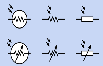
Circuit symbol of photoresistor:
MG: stands for photoresistor
0: Special photoresistor
1, 2, 3: UV photoresistor, UV: used in UV detection instruments.
4, 5, 6: Visible light photoresistor, visible light: various photoelectric automatic control systems, electronic cameras and light alarms.
7, 8, 9: Infrared light photoresistor, infrared: used in automatic control systems in astronomy and military fields.


 Need Help?


